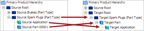
The Application Mapping plugin will move applications from the Source object to the Target object, as well as establish references for the Target applications to Target vehicles and Target part types. The Application Mapping plugin is added and configured in the Onboarding Mappings Details Screen for the selected Mapper Configuration.
Prerequisites
Before creating the Application Mapping plugin, the following items must be done:
- Determine what the Source object is that applications currently exist below
- Determine what the Target object is that applications should be created below by the Application Mapping plugin
- Ensure that the Source application has references to a vehicle and a part type
- Establish the reference between the Source part and the Target part
- Establish the reference between the Source vehicle and the Target vehicle
- Establish the reference between the Source part type and the Target part type
- Create and configure the Onboarding Mappings Details Screen (here)
- Create the Mapper Configuration (here)
Configuring Application Mapping Plugin
To configure the Application Mapping plugin, follow these steps:
- In Web UI, select a Mapper Configuration and after the Setup tab has been configured, click on the New mapping option that is available in the Mappings tab of the Onboarding Mappings Details screen.
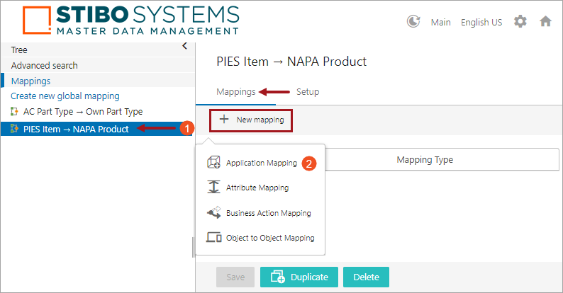
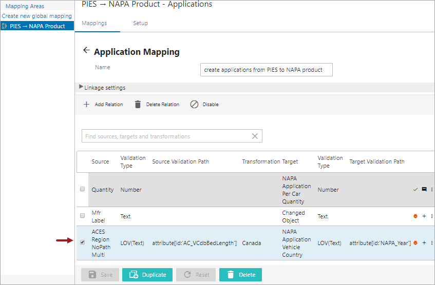
- Select Application Mapping, and a screen will be displayed prompting the user to further configure the plugin. Below is a screenshot of the Mappings tab in the Onboarding Mappings Details screen. The steps required to configure the Application Mapping are denoted with a number in the screenshot. Below the screenshot is a numbered list that describes each step, corresponding to the number shown in the image.
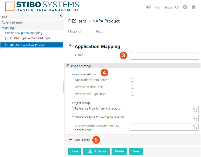
- Type in a suitable name next to the Name field. This could be any unique name that describes the mapping functionality.
- Populate the parameters available under the 'Linkage settings' flipper as explained below:
-
Common Settings: Define the following optional parameters. The available options are:
- Applications from parent: Selecting this parameter will select applications from the parent of the Source object to share applications between multiple parts. This option can be selected in some special cases where Source applications lie directly below the parent of the Source part (i.e., applications and the Source part are in the same level of the hierarchy). The Target applications will be created below the Target Part.
- Reverse Vehicle Links: Selecting this option will reverse the direction that will be used to find the vehicle. The actual direction is defined in the 'Reference type for Vehicle relation' field. This is the same as selecting the target object and using the [Referenced By] option.
For example, if the source object = NAPA Product and applications belonging to this source object need to be mapped to target object = PIES Item, and the reference type for vehicle relationship is referenced from source object vehicle = NAPA Year to target object vehicle = Base Vehicle. If the Setup now needs to have source object = PIES Item and applications in the PIES Item need to be mapped to target object = NAPA Product, then the Reverse Vehicle Links is used to find the vehicle relationship.
- Reverse Part Type Links: Selecting this option will reverse the direction that will be used to find the part type. The actual direction is defined in the 'Reference type for Part Type relation' field. This is the same as selecting the target object and using the [Referenced By] option.
For example, if the source object part type = NAPA MPCC and it is mapped to target object part type = Part Terminology, then selecting the Reverse Part Type links option will be used if the source object part type = Part Terminology and the target object pat type = NAPA MPCC to find the part type relationship.
-
Object Setup: Define the following parameters. The available options are:
- Reference type for Vehicle relation: Defines which reference type to use to look for the vehicle relationship from the source to the target vehicle.
For example, if the source object = NAPA Product and applications belonging to this source object need to be mapped to target object = PIES Item, then the reference type for vehicle relationship is referenced from source object vehicle = NAPA Year to target object vehicle = Base Vehicle.
- Reference type for Part Type relation: Defines which reference type to use to look for the part type relationship from the source to the target part type.
For example, if the source object = NAPA Product and applications belonging to this source object need to be mapped to target object = PIES Item, then the reference type for part type relationship is referenced from source object part type = NAPA MPCC to target object part type = AutoCare Part Terminology.
- Business action executed on new applications: This field will allow the selection of a Business Action to be executed on the applications that will get created.
- Click the ‘Add Relation’ icon, and the Mapping Guide window will display. Adding a relation can be as simple as copying an attribute value from the Source application over to the Target application. Or for any condition(s) that can be retrieved on the Source object by following references or attributes can also be added as a relation to the Target object in order to map the applications (only if the valid relations are covered).
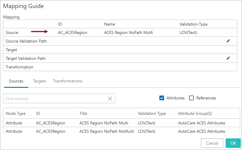
- To add an attribute relation, select the Sources tab, select the Attributes option, click in the Search field and start typing the initial letters of the attribute name or ID. This will display a dropdown of typeahead search results listing the attributes that are valid for the objects that are defined as the Source object. Select the attribute from the result list displayed below the search bar.
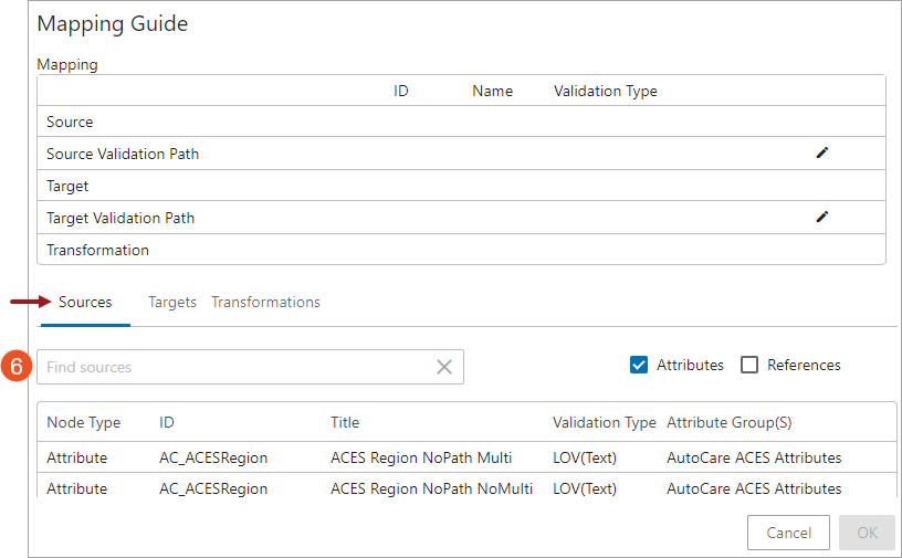
Once selected, the attribute will be populated in the Source field (as shown below)
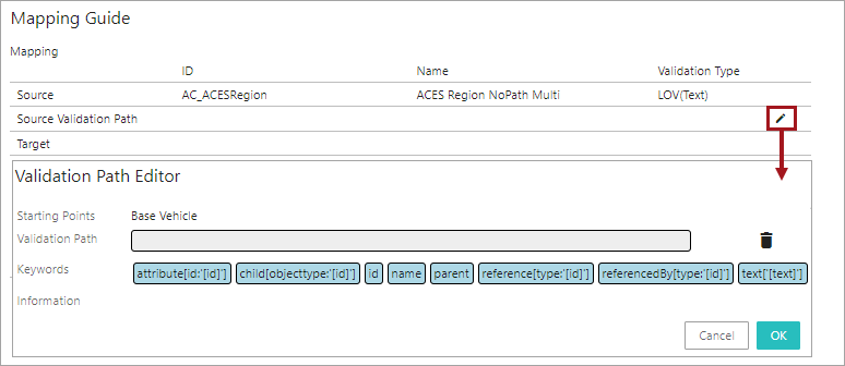
- In addition, if any other information (ID, Name, attribute values, references or links) from the Source object needs to be retrieved, click on the Edit icon (
 ) in the Source Validation Path field, and the Validation Path Editor window will display (as shown below). The user also has the option to select specific data points fromthe Source object, or any of its related objects by selecting a combination of the elements available in the Keywords field and thereby creating a STEP Validation path. For more information on defining the Source STEP Path, see the Mapping Validation Path Functionality topic within this guide here.
- Double click on the required element(s) from the Keywords field. The selected element will be populated in the Validation Path field (as shown below). The specific combinations of elements are chosen depending on the unique requirements for the data being retrieved. Selecting the elements will define the Source STEP Path which describes the path from which the source data must be retrieved. Depending on the element that is selected, further configurations may be required. In the example below, element attribute[id:'[id]'] is selected and displays in the Validation Path field. The red colored field indicates that additional configuration is required.
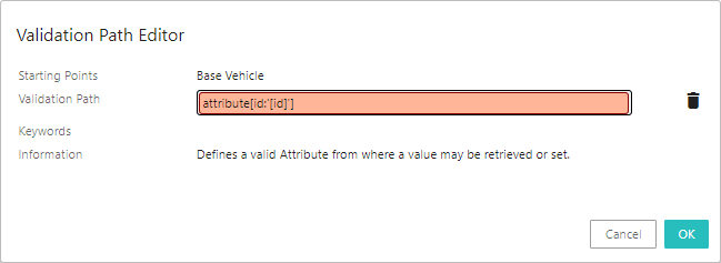
Users can add one element or a combination of elements to create a Source STEP Path. For more information on creating the Source STEP Path, see the Mapping Validation Path Functionality topic within this guide here.
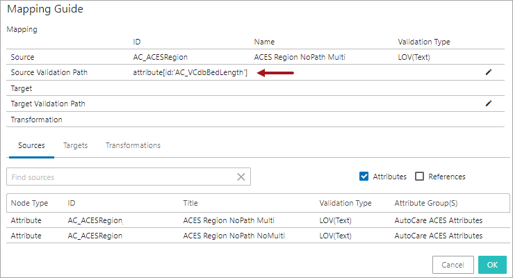
In this example, the selected element 'attribute[id:'[id]']' is configured to retrieve the value from attribute with ID 'AC_VCdbBedLength'.
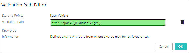
Once selected, the Source STEP Path with the defined data will be populated in the Source Validation Path field.
- With the 'Targets' tab selected, click in the Search field and start typing the initial letters of the attribute / reference name or ID of the target attribute / reference to which the value should be copied. Select the attribute / reference from the typeahead results displayed below the search bar.
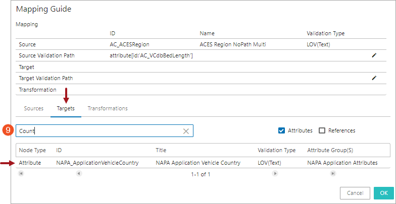
Once selected, the selected attribute / reference will be populated in the Target field (as shown below).
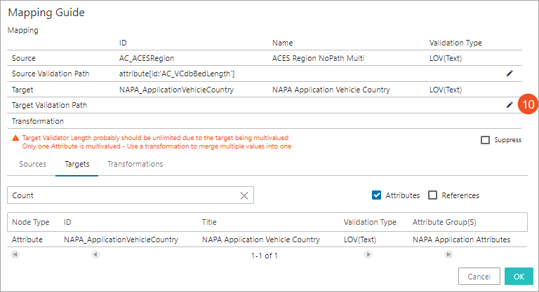
- In addition, if the retrieved information from the Source object needs to be populated in the Target object or any of its related objects (in the form of ID, Name, attribute values, or references), click on the Edit icon () in the Target Validation Path field, and the Validation Path Editor window will display. The user has the option to select specific data points of the Target object, or any of its related objects by selecting a combination of the elements available in the Keywords field and thereby creating a STEP Validation path. For more information on defining the STEP Path, see the Mapping Validation Path Functionality topic within this guide here.
Note: Only attributes / references that are valid for the object type that is defined in the mapping Setup tab will be displayed as options to select from in the Source, Source Validation Path, Target, and Target Validation Path tabs.
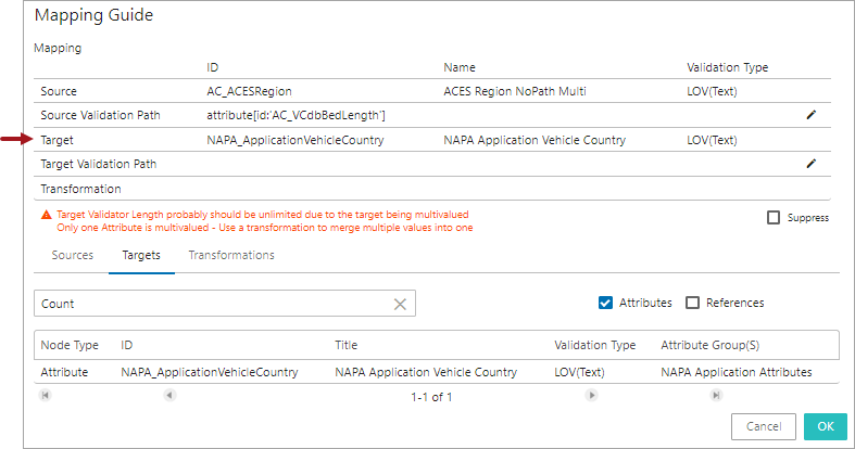
After the Source STEP Path and target attribute / reference are defined, the system evaluates the validity match between the Source STEP Path and the Target attribute / reference. A hyperlink text explaining the reason for the validity match / mismatch will be displayed. Clicking on the hyperlink opens the 'Detailed Information' dialog which displays the validity match / mismatch information of the Application mapping configuration. Below is an example of an invalid match between the Source and the Target attribute that is displayed in the 'Detailed Information' dialog.
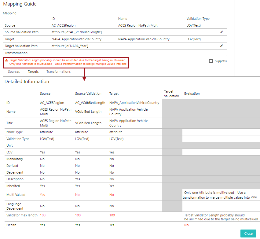
Users can suppress the validation mismatch warning message by clicking on the 'Suppress' checkbox in the Mapping Guide window. Selecting the 'Suppress' checkbox only removes the data type mismatch warnings displayed on the Mapping Guide window and does not resolve the mismatch irregularities.
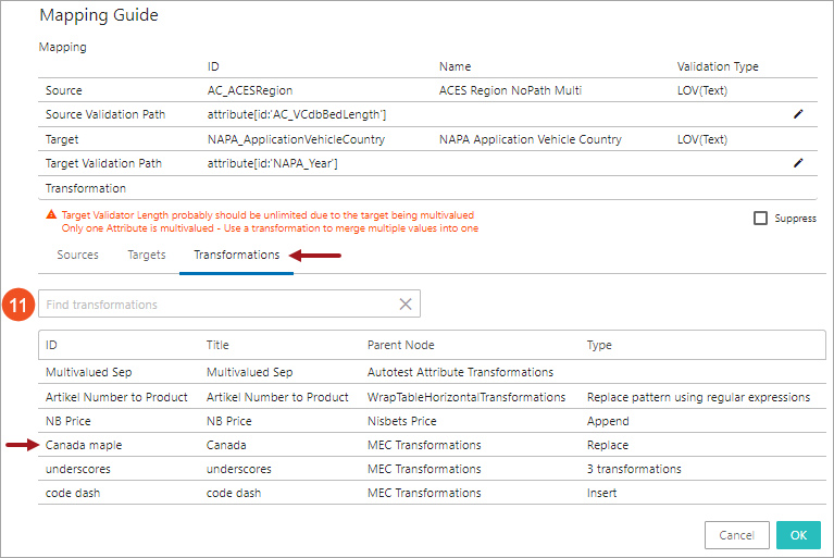
- If transformations are needed, select the Transformations tab, click in the Search field and start typing the initial letters of the transformation name or ID. This brings up a dropdown of typeahead search results listing the attribute transformations that are available in the system. Select the relevant transformation from the list displayed below the search bar.
Note: The transformations must be created and defined in the workbench System Setup prior to being available to be selected in the Mapping Guide.
The selected transformation will be populated in the Transformation field (as shown below).
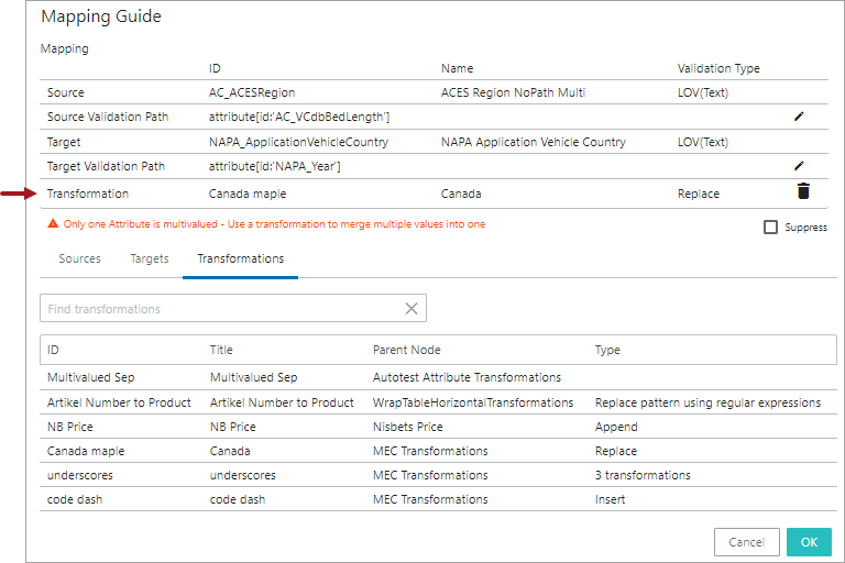
For information on configuring the attribute transformations, see the Attribute Transformations topic within the System Setup section of STEP Online Help (here). And for details on each of the available transformation options, see the Transformations topic in the Resource Materials online help here.
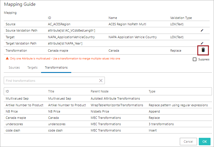
The populated transformation can be deleted by clicking the delete icon (![]() ) in the 'Transformation' field.
) in the 'Transformation' field.
- Click OK to save and close the 'Mapping Guide' window and then click Save to save the changes. As shown in the screenshot below, the newly added application mapping row will be displayed. To edit the application mapping, click on the row to open the Mapping Guide window in which edits can be made.
Note: Once the user adds a mapping and selects the Source STEP Path and Target and clicks OK to close out of the Mapping Guide window, the Save button is enabled until the user clicks on the Save button. If the user fails to click Save, then the mapping will be lost once the user selects a new mapping configuration.
- Repeat the above steps 5 to 12 to add more application mapping rows for the same plugin.
Users can add any number of mapper rows in the mapping plugin. When there are multiple mapper rows available within the mapping plugin, the order of execution of each mapper row is based on the order in which it is listed within the mapping plugin.
The health of the mapping row is displayed towards the right of each row. Users can also add some additional information describing each of the mapper rows. The user has the flexibility to disable, delete, or rearrange the listing order of the mapper rows. For more information on handling the mapper rows, see topic Modifying Mapper Rows on the Onboarding Mapping Details Screen within this guide here.